bGeigie Nano part 1 (unboxing the kit)

The bGeigie nano is an updated and smaller version of the original bGeigie nuclear radiation monitor and geo-referenced radiation mapping device. These devices were developed by the Safecast organization to provide radiation monitoring and data mapping by and for the public.

The kits were offered for pre-order recently, so I signed up on the waiting list and was able to get one in the first batch of kits provided in the US by International Medcom. The kit arrived at the end of June (they sent a resistor to change out an incorrect value part in the kit a few days later) and It’s finally time to open the box after about a month on the shelf.

The first video in a series on the bGeigie nano, unboxing and discovering what parts are in the kit.

To get your own bGeigie nano kit, see this page at International Medcom.

A Serial Bootloader for Microchip 8 bit PIC Embedded Designs: Microchip Application Note AN1310

This article introduces the reader to a set of up to date Serial Bootloader tools for Microchip 8 bit PIC series products that we frequently use in electronic designs featuring an 8 bit embedded MCU (Micro Controller Unit).

So what is a Serial Bootloader and why would anyone want it?

In some products that use an MCU it may be advantageous to allow the program to be updated in the field or at a service shop without the specialized programming gear needed to completely reprogram it. For this purpose the MCU is equipped with a small primary program whose sole purpose is to facilitate updating of the main device application program.  In embedded systems this is sometimes referred to as a “Bootloader Stub” since it is often located at the beginning or end of the program memory space, and is the first code to execute on start or reset.  When the device starts, the Bootloader checks for a special state or instruction.  If that object is present, the Bootloader waits to download and overwrite the Application Program with an update.  Otherwise the device continues on to execute the full Application Program.  Some such devices have a USB port that can be used as the communications for this but it is less common than other serial port types that can be implemented at lower cost. One of the most common serial port types on low cost embedded designs is the venerable RS-232 port. In fact, many different MCU devices have one or more built in UART devices (direct support for RS-232) while just a handful build in the more complex USB port.

For example: recently tasked with redesigning a controller PCB for an existing product, there was no need or desire to change the interfaces, only update the components that were obsolete. One of the obsolete components was the Microchip MCU, a 40 PIN DIP with insufficient Flash memory for program updates and a shortage of digital I/O. It was replaced by an 80 pin TQFP variant with more memory space in all 3 categories (Flash, RAM and EEPROM) more I/O of course (to eliminate the previous I/O sharing scheme and provide for expansion) and perhaps most important at a lower cost than the old part it replaces. A dedicated ICSP (In Circuit Serial Programming) port replaces the practice of burning the old DIP parts in in an old EEPROM programmer appliance. The product also uses an RS-232 port to communicate with a control computer. In this case, it was decided to leverage the existing RS-232 port in the design for firmware maintenance. The larger Flash space of the new MCU allowed adding the Serial Bootloader feature to eliminate the need for any dedicated programmer equipment when updating units already programmed at least once. All that is needed is a PC to run the AN1310 PC Bootloader application equipped with a RS-232 serial port, an established serial link between the computer and device to be programmed and the program update in the form of a .hex file.

The Application Note from Microchip, AN1310 provides all of the resources needed to accomplish the addition and operation of the Serial Bootloader with many variants of the PIC16F and PIC18F 8 bit MCU families having an available UART port.

Microchip AN1310

Doubling Down with the PIC32

In an earlier post, A high density Automotive control design using the Microchip PIC32MX MCU was described. That design was a great success. However, as with all things new it was found to be in need of more I/O. The circuit board was revised to double all of the digital and analog peripheral I/O while retaining the same overall PCB outline of 5″x7″. it was also kept to just 2 layers and components on only one side, again with the help of the peripheral circuitry simplicity afforded by the Microchip PIC32MX360F512L MCU.

An update to a recent PIC32 Control System Design

While it is a bit more dense that the previous revision, it still fits without too much crowding on the 5″ x 7″ 2 layer PCB.

Vernon Johnson, Engineer LLC

PIC32 SPI to MCP4922 Dual 12 bit Digital to Analog Converter

Reposted from Vernon’s Excellent Blog (original date 12/16/2011).

I recently completed an exercise in bringing up a MCP4922 DAC on the PIC32 SPI. I didn’t find any examples specifically using the PIC32 with MCP4922 or even any examples of the MCP4922 used in a 3.3v circuit. Therefore I thought a post might help the next fool that comes along and tries it…

1. The PIC32 Peripheral Library Help file is not much for detail, I found a need to dig into the SPIxCON register table in the PIC32 datasheet just to get definitions for the Input Parameter Mnemonics.

2. The CLK and SDO lines both need to be pulled up with at least 10K (I ended up using 4.7K). Further design refinements included pull ups on CS and LDAC with 10K to ensure sufficient loading on the PIC32 outputs, .01uf bypass caps on the outputs to filter the switching noise out and closer coupling of the MCP4922 P/S bypass caps to 4mm or less from the Vdd pin as recommended in the datasheet.

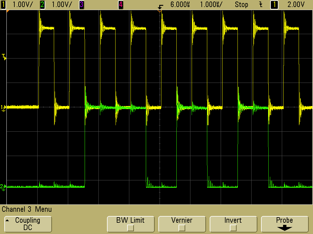
3. When halting just after a TX everything worked OK but it got unstable when I let it run free at an update rate of 10HZ or even slower. After much troubleshooting (including assuming that I had damaged the DAC chip) scope trace snapshots revealed the instability was due to a data/clock sync error. Specifically the clock burst was terminating early on random data write events. I found that it requires the CKE transition to be inverted (CKE = 1, [SPI_OPEN_CKE_REV]) to shift data out before the clock to run stable. Indeed, now it runs smooth and clean at a 1MHz SPI clock rate. YAY!

Here’s the SetDAC Function (Written in C32 v2.01)

SetDAC_PIC32_MCP4922.txt

And now it works!

Clock and Data Waveforms @ 1MHz

Clock and Data Waveforms @ 1MHz

Happy Coding…

New Developments in Embedded Systems

The circuit pictured here is a custom control device for an automotive application.  While the detail of the application is confidential, some common knowledge facts are significant to note for anyone interested in the current state of the art in this field.  It encompasses several recent advancements in Embedded Control System integration.  At the heart of the circuit is the Microchip PIC32MX360F512L, a 32 bit MCU implementing the MIPS 32 architecture in a highly integrated single IC.  The system includes a full compliment of analog and digital I/O with a minimum of external circuitry.

A recent PIC32 Control System Design

For example: The Power Outputs are a good example of the simplicity available today.  The large double sided copper lands at center right are actually all the heatsink needed by the power MOSFET output drivers to support output currents of 3A per channel.  Those Power FETs are driven directly by the MCU.

While the PIC32MX is a 3.3v device, the outputs are “5v Tolerant”.  This feature facilitates things like driving the Power FETs directly.

Another nice feature is the capability to perform some DSP style filtering.  This allows the electronic signal filtering on the Analog Inputs to also be minimized.

The PIC32MX is provides an excellent mix of full features and low cost. While it may cost a bit more than the venerable 8 bit MCUs that still dominate the sector, I am finding a general ability to design with fewer external support components that offsets some of the cost. It also helps to have more headroom for programming. In some cases that turns out to be a more significant cost factor than the parts.

Vernon Johnson, Engineer LLC